ppt download Circuit Diagram Active LOW vs. Active HIGH Relays. Relay modules can be configured as Active LOW or Active HIGH, depending on their design.. Active LOW: The relay is activated when the control signal is LOW (0V). Active HIGH: The relay is activated when the control signal is HIGH (5V). To determine the type of your relay module: Check the Manufacturer's Datasheet: Look for the module specifications.
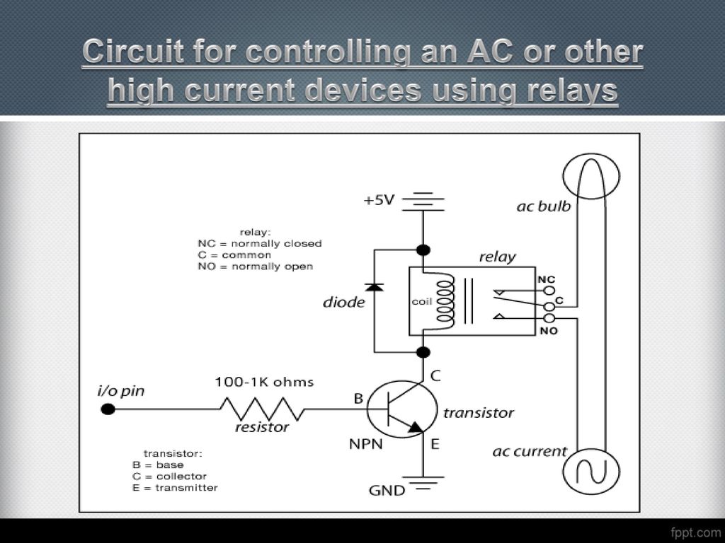
A relay requires a low voltage (e.g. 5v, 12v) to turn on the relay switch. You can use that switch to control high-voltage appliances. So we can control a relay (5v relay) switch using the Arduino output pin. On the other side, we can connect a high-voltage device (e.g. a 240v bulb) to control it. Introduction to Relay Module

Arduino Relay Tutorial: Control High Voltage Devices with Relay Modules ... Circuit Diagram
Please click this link to see the full article: http://www.allaboutcircuits.com/projects/use-relays-to-control-high-voltage-circuitswwith-an-arduino/Circuits
Before we begin, we must know what is the relay how it works before we use it to power high voltage devices. The relay module is an electrically operated switch that can be turned on or off deciding to let current flow through or not. They are designed to be controlled with low voltages like 3.3V like the ESP32, ESP8266, etc, or 5V like your

Use Relays to Control High Voltage Circuits with an Arduino Circuit Diagram
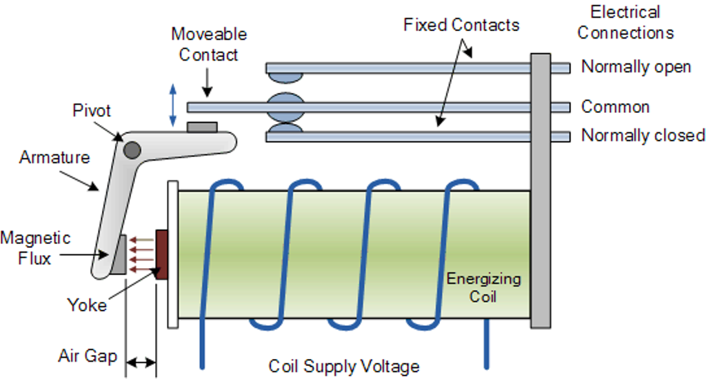
Instead, you use a low-voltage control signal from the Arduino to control a relay, which is capable of handling and switching high-voltage or high-power circuits. A relay consists of an electromagnet that, when energized, causes a switch to close or open.

As an example for this Arduino Relay Tutorial we will use the HL-52S 2 channel relay module, which has 2 relays with rating of 10A @ 250 and 125 V AC and 10A @ 30 and 28 V DC. The high voltage output connector has 3 pins, the middle one is the common pin and as we can see from the markings one of the two other pins is for normally open
